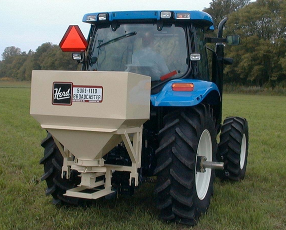


Herd’s model 1200C is a proven Workhorse. With 1200 pounds and 16 bushel capacity, the model 1200C will give you both convenience and durability. Our 3‐point mounted broadcasters allow you to seed anywhere your tractor can go, saving both time and money. With Herd’s precision metering system, the amount of seed can be controlled from 3 pounds of seed per acre to 1000 pounds of fertilizer per acre. The model 1200C can be broadcast both seed or fertilizer with no parts to change or modifications to make.
- 3‐point Mounted, with shielded telescoping PTO
- Round Hopper Base prevents lodging of material
- 14‐gauge steel hopper with powder coat paint and welded seams
- Quick Hitch compatible
- Easy‐Adjust Pattern Control for even spreading up to 40 feet wide
- 16 bushel (1200#) capacity
- Options include lime agitator, hydraulic or electric open/close system, hydraulic drive system, skid steer mounting plates, or banding kits for vineyard or nursery spreading
- Amount of Spread per Acre of Seeds can be Controlled down to 3#
- Fertilizer can be spread from 50# to 1000# per acre
- No Special Parts needed to Change from Seed to Fertilzer
- Rotating Agitator and Fan driven by Heavy-Duty Gearbox
- Heavy Cast Iron Gearbox has tapered roller bearings, drop forged gears
- Gearbox is Standard for 540RPM but can be ordered for 1000RPM
- Can Also be Used for Spreading Calcium or Salt on ice or snow
WARNING: To avoid serious injury or death, additional tractor front ballast may be
needed for stable operation and transport of the drill/seeder. See tractor operator’s
manual for recommended weights.
WARNING: To avoid serious injury or death, never stand between tractor and seeder
while tractor is being backed to hitch.
- Carefully and thoroughly read this owners manual.
- The gearbox is shipped from the factory with one pint of 90 weight gear lubricant. Before using the broadcaster, check for the proper level. Remove the fill plug on the gearbox. The oil level is sufficient if the oil is at or just above the plug hole. If the level is low, fill the gearbox with 90 weight gear lubricant to plug hole level.
- Cut the two wires holding the power take off shaft to the broadcaster for shipping. Remove the tape from the gearbox shaft and clean any paint on shaft. Place the 1” hole end of the power take off shaft over the gearbox shaft and insert the 5/16” x 2” spring pin provided. As an extra precaution, a wire can be run through the spring pin and around the hub of the power take off shaft to secure the spring pin.
- CAUTION Ensure that the PTO shaft is not too long before raising the seeder with the 3‐point hitch of the tractor. If it is too long, this will cause damage to the gearbox. If the PTO shaft is too long, you will need to cut equal amounts off both ends of shaft before raising the seeder on the 3‐point hitch and attaching upper center link arm to the seeder
- To Assemble handle (FIG 1): Cut wires located at the top and bottom, holding handle against broad caster in shipment. Remove the nut on the eye bolt. Loosen the 5/16” x 1” bolt-on lower handle bracket. Move the handle away from the broadcaster and retighten the 5/16” x 1” bolt. Remove the 5/16” x 1” bolt in angle. Using this bolt, bolt the upper handle bracket to an angle. Tighten all bolts tight, ensuring that they are setting at a right angle to the broadcaster. Replace spring tightener for good tension. This spring works with the handle and will hold the opening gate in either an open or closed position.
- Make sure that handle and opening plate operate freely.
- The broadcaster is now ready to mount on tractor with three‐point hitch.
- Lift arms should be set for Category 1, or 26‐7/8” spacing. Sway bars, blocks, or chains must be used to keep the broadcaster from swinging sideways.
- Remove or move drawbar to side position so as not to interfere with power take off shaft.
- Install on two lower arms first, then attach power take off shaft, then hook up center arm.
- CAUTION: When raising the broadcaster for the first time, make sure the power take off shaft does not bottom out, or that the power take off shaft is longer than the distance between tractor and seeder. If it does bottom out, it will cause the gearbox to break and will damage the fan. If power take off shaft is too long, cut off equal amounts on both the male and female ends of shaft.
- Raise broadcaster up so the power take‐off shaft runs fairly straight or level. For best results, center linkage should be shortened until the broadcaster top tilts a little forward towards the tractor.
- You determine the right or left side of broadcaster by standing at the rear of the tractor and facing the direction of the tractor’s travel.
- The broadcaster has a circular plate (part #144) bolted to the base of the hopper that is adjustable, for centering the spread pattern. This plate is numbered from 1 to 9 and the numbers are found on the back side, on the opposite side from the seed opening gauge (part #146). To move the adjustable plate, loosen the four bolts (part #418). Always be sure to retighten bolts after adjustments are made to the plate. The normal setting for fertilizer is on number 3‐1/2, and may be moved to a high or lower number depending on the weight and quality of the fertilizer. CAUTION: DO NOT MAKE ANY ADJUSTMENTS TO BROADCASTER WHILE THE TRACTOR OR BROADCASTER ARE RUNNING.
- When the spread pattern is heavy on the right side, move the base plate (part #144) to the right (clockwise) to a higher number. Do not move over one number before checking or you may overcompensate.
- When the spread pattern is heavy on the left side, move the base plate (part #144) to the left (counter‐clockwise) to a
- lower number. Do not move over one number before checking or you may overcompensate.
- Make sure the bolts are tightened evenly after making adjustments.
- The width of the seed‐gate opening is controlled by the seed gauge (part #146), which is bolted to the circular plate (part #144). The seed gauge is marked in 1/8” markings for your convenience. If the seed gauge moved back 1/2” from 0, the seed‐gate opening will likewise open 1/2”. To verify the seed‐gate opening accuracy, insert a drill bit of the de‐ sired fraction of an inch between the seed‐gate and the edge of the base plate (part #144).
- The handle assembly (part #212) is spring‐loaded with an over‐center design. When pushed, it will close the seed‐gate and when pulled it will open the seed‐gate. The double‐nutted bolt that attaches the handle assembly to the seed‐gate linkage should not be tightened because it must move freely in the seed‐gate linkage slot to work properly.
- When broadcasting small seed at small amounts per acre, an optional special seed‐gate is available. This is part #148S.
NOTES:
*** Any Model With Hydraulicly Controlled Banding Kits:
-Requires 8” stroke ASAE hydraulic cylinder with 28-3/8” extended length. Cylinder & hoses Not Included.
-Requires 8” stroke ASAE hydraulic cylinder with 28-3/8” extended length. Cylinder & hoses Not Included.
-Throws to both left and right sides at all times
*** Any Model With Manually Controlled Banding Kits:
*** Any Model With Manually Controlled Banding Kits:
- Throws to left side, to right side or both sides.
- No Additional Kits Required For Use
PARTS DIAGRAM MODELS 1200C