


HERD Model 550-3PT Broadcast Seeder & Spreader For Tractor
HERD Model 550-3PT Broadcast Seeder & Spreader For Tractor
Couldn't load pickup availability
Couldn't load pickup availability


Product Description
HERD Model 550-3PT Broadcast Seeder & Spreader For Tractor
DISCRIPTION
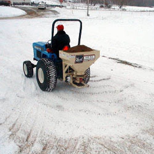
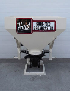
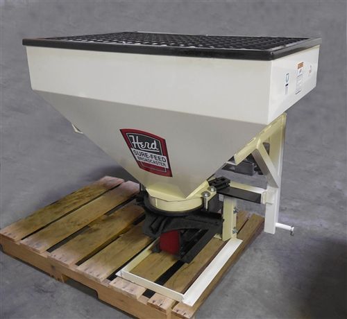
The HERD Model 550-3PT Broadcast Seeder & Spreader is a versatile, compact seeder ideal for small tractors on estates, parks, and small farms. Designed with a low-profile hopper, this seeder is easy to fill and maneuverable. It offers a 5-bushel (550 lb) capacity and can spread various materials, including seeds, fertilizer, calcium, or salt, up to 40 feet wide. The heavy-duty 14-gauge steel hopper and cast iron gearbox ensure long-lasting performance.
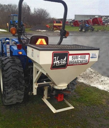
The 550-3PT model is engineered for ease of use, featuring a 3-point hitch mounting system with a shielded PTO and adjustable spreading controls. Its round hopper base prevents material from lodging, while the precision seed gate controls enable accurate spreading rates. Whether spreading small seeds or high amounts of fertilizer, the HERD Model 550-3PT is a reliable solution for various agricultural and maintenance tasks.
Key Features
- Optimized for Compact Tractors: Suitable for compact tractors on small farms or estates.
- Precision Seed & Fertilizer Control: Adjustable controls for spreading from 3 lb to 1000 lb per acre.
- Robust Gearbox Construction: Equipped with a cast iron gearbox, tapered bearings, and forged gears for reliable operation.
- Versatile Material Compatibility: Can spread seed, fertilizer, salt, or calcium on ice or snow.
- Effortless Cleaning: Easy-to-clean design with no parts to remove or lose.
- Adjustable Pattern Control: Even spreading up to 40 feet wide with easy-to-use pattern controls.
Detailed Specifications
| Feature | Description |
|---|---|
| Capacity | 5 bushels (550 lb) |
| Hopper Material | 14-gauge steel, powder-coated with welded seams |
| Spread Width | Up to 40 feet |
| Pattern Control | Easy-adjust pattern control |
| Mount Type | 3-point mounted, Category 1 compatible |
| Gearbox | Cast iron with tapered roller bearings, drop-forged gears |
| RPM Options | Standard 540 RPM; optional 1000 RPM |
| Compatibility | Seed, fertilizer, salt, calcium |
| PTO Shaft | Shielded telescoping PTO shaft |
| Gate Control | Spring-loaded handle for precise seed gate adjustment |
| Additional Options | Special seed gate for small seeds (optional) |

In Package:
- HERD Model 550-3PT Broadcast Seeder & Spreader
- 14-gauge steel hopper with powder coat finish
- 3-point hitch mounting kit (Category 1)
- Cast iron gearbox (540 RPM standard)
- Shielded telescoping PTO

Manuals & Documents
General Warranty Info:
- Ripping It Outdoors works closely with our manufacturers to supply and support your products warranty needs as best as possible!
- The majority of products come with a manufacturer represented warranty against manufacturing defects for at least a 12 month period after the date of sale.
- Expendable components and "wear parts" including but not limited to blades, knives, teeth, oil, chain sprockets, skid shoes, knife mounting discs, and similar components are usually excluded from manufacturer warranties.
- Please reach out to us for any specific warranty information needed about products and parts you can’t find!
Videos
Shipping
General Shipping Info:
- Instantly calculate shipping quotes to the lower 48 states by 1. adding this product to your cart, 2. click continue to the checkout page and 3. enter your shipping address to check rates. Contact us for quotes for shipping to Hawaii, Alaska, Canada, Mexico and Internationally.
- Complimentary lift gate service on all freight shipments where it’s possible. We guarantee safe delivery!
- Low shipping rates for customers. We have negotiated the best possible rates for customers from our trusted carriers (ODFL, ESTES, UPS, and FedEx).
- Negotiate shipping rates if you think we can do better please reach out. Keep in mind some shipping rates also include assembly & configuration as well!